

Future technologies can further improve the accuracy and stability of dynamic trajectory lines through various approaches, including the following aspects:
Integration of Historical Predictions and Attention Mechanisms
As demonstrated by the HPNet method, introducing a historical prediction attention module can automatically encode dynamic relationships between consecutive predictions, thereby enhancing prediction stability and accuracy. This approach not only utilizes historical frames but also considers historical prediction results, making the predicted trajectories more consistent and reliable.
Optimization of Control Algorithms
In intelligent vehicle trajectory tracking, the combined use of LQR and PID control algorithms can significantly improve the control accuracy and stability of vehicle trajectory tracking. An improved LQR control algorithm, integrated with genetic algorithms for parameter determination and PID control for enhancing longitudinal speed control accuracy, can reduce lateral and heading deviations.
High-Precision Trajectory Generators
With advancements in fluid-floated, laser, electrostatic, and MEMS gyroscope technologies, as well as the emergence of new gyroscopes such as quantum and nuclear magnetic resonance types, the accuracy of inertial navigation algorithms will continue to improve. The demand for high-precision trajectory generators will become more evident. In the future, convenient, flexible, and high-precision trajectory generators will play a crucial role in high-precision INS research.
Application of Kalman Filtering
The dynamic trajectory prediction algorithm based on Kalman filtering performs state estimation of moving objects' dynamic behavior. It updates the state variable estimates using previous estimates and current observations to predict trajectory positions at the next moment. This method addresses the issue of low trajectory prediction accuracy while ensuring prediction timeliness.
Real-Time Tracking Technologies
In the field of railway transportation, comprehensive monitoring of train operational status can be achieved by leveraging advanced technologies such as Global Positioning System (GPS), Automatic Train Control (ATC), wireless communication, and Geographic Information Systems (GIS). Building a robust system architecture, including data acquisition, processing, transmission, analysis, and visualization layers, is key to realizing real-time tracking. Although challenges such as signal interference, data delays, and system security exist, reasonable solutions can ensure system stability and reliability.

Utilization of Environmental and Semantic Information
One of the future directions for trajectory prediction is leveraging more environmental and semantic information to enhance the reliability of prediction results. Combining different types of prediction methods can improve the accuracy of these results.
Utilization of Environmental and Semantic Information
In trajectory prediction, another important research direction is leveraging social rules and psychological models to enhance the interpretability and reliability of trajectory predictions.
Uncertainty Quantification and Risk Assessment
By utilizing uncertainty quantification and risk assessment, the safety and stability of trajectory predictions can be ensured.
In summary, future technologies can further enhance the accuracy and stability of dynamic trajectory lines by integrating advanced control algorithms, high-precision trajectory generators, Kalman filtering, real-time tracking technologies, and the utilization of environmental and semantic information.
What Is the Specific Impact of Camera Installation Position on the Accuracy of Dynamic Trajectory Lines?
According to multiple technical analyses and test reports, the position of the camera not only determines the display effect of the trajectory lines but also directly affects their consistency with the actual reversing path. Here is a detailed analysis:
Impact of Camera Installation Position on Trajectory Line Display
In the Desay SV2311 reverse camera system, the installation position of the camera is closely related to the accuracy of the dynamic trajectory lines. Tests show that the trajectory line on the passenger side generally aligns well with the actual reversing path, while the trajectory line on the driver's side exhibits certain deviations, especially when turning the steering wheel clockwise. This indicates that the camera's installation position affects the display effect of the trajectory lines, thereby influencing the driver's judgment.
Impact of Camera Installation Angle on Trajectory Line Precision
If the trajectory lines are built into the camera, the installation angle of the camera directly affects the precision of the trajectory lines. Since the installation height of rearview cameras varies across vehicles, the distance indicated by the trajectory lines will also differ. Therefore, if the camera installation angle is incorrect, the indicated distance of the trajectory lines may deviate, making it difficult for the driver to accurately judge the distance between the wheels and obstacles. Additionally, if the camera installation position is offset, the display effect of the trajectory lines may be compromised, potentially leading to inconsistencies between the trajectory lines and the actual reversing path.
Impact of Camera Installation Position on Trajectory Line Generation
The generation of dynamic trajectory lines relies on the camera's perspective and image quality. If the camera is installed in the center of the rear of the vehicle, it can achieve the best perspective and image quality, ensuring the accuracy of the trajectory lines. Conversely, if the camera is installed improperly, such as on the driver's side license plate light, it may cause deviations between the trajectory lines and the actual reversing path. This is especially true in complex road conditions, where drivers may misjudge the situation.
Impact of Camera Installation Position on Overall System Performance
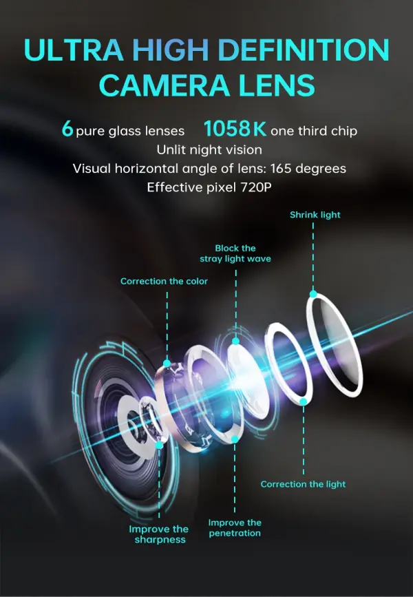
Beyond the display effect of the trajectory lines, the camera's installation position also affects the overall performance of the reverse camera system. For example, if the camera is installed in the center of the rear of the vehicle, it ensures the clarity and stability of the reverse image, thereby improving the accuracy of the trajectory lines. If the camera is installed improperly, it may cause image blurring or distortion, affecting the judgment of the trajectory lines. Additionally, the camera's installation position influences the trajectory line generation algorithm. For instance, in Tesla's FSD system, the installation positions of the B-pillar side cameras and the rearview camera need to be precisely coordinated to ensure the generation of dynamic trajectory lines.
Impact of Camera Installation Position on User Operation
Since the camera's installation position affects the accuracy of the trajectory lines, users need to consider the vehicle model and camera installation position when purchasing or installing a reverse camera system. For example, if the camera is installed on the passenger side, the trajectory lines will generally align well with the actual reversing path. However, if it is installed on the driver's side, deviations may occur. Therefore, users should ensure that the camera's installation position matches the vehicle model to achieve the best user experience.
In conclusion, the installation position of the camera has a significant impact on the accuracy of dynamic trajectory lines. A correct installation position ensures consistency between the trajectory lines and the actual reversing path, enhancing driving safety. Conversely, an incorrect installation position may cause deviations in the trajectory lines, affecting the driver's judgment. Therefore, when selecting and installing a reverse camera system, careful consideration should be given to the camera's installation position to ensure the accuracy and reliability of its functionality.
What Are the Sources of Error in Dynamic Trajectory Lines Under Different System Implementation Methods?
Independence of Servo Control
In multi-axis CNC machine tools, the servo control of each feed axis is performed independently. This independence may cause deviations in the end position relative to the commanded position in each feed direction, leading to deviations in the linkage trajectory.
Gyro Drift and Accelerometer Zero Error
In strapdown inertial navigation systems, gyro drift and accelerometer zero error are the main sources of dynamic error. These errors affect system accuracy, especially when the carrier is in motion.
Dynamic Tracking Error Between Measurement System and Target System
In spaceborne InSAR baseline configurations, dynamic errors mainly originate from the dynamic tracking error between the measurement system and the target system. This includes measurement errors of the measurement device, mechanical vibrations during orbital operation, and minor disturbances such as thermal-induced tremors.
Signal Distortion
In CNC machine tools, contour errors are often caused by signal distortion in the position loop. Signal distortion can be divided into linear distortion and nonlinear distortion. Causes of linear distortion include suboptimal settings of speed or position controllers, differences in following errors of axes involved in the trajectory, and differences in dynamic responses of feed drives. Causes of nonlinear distortion include current limiting, speed setpoint limiting, reverse dead zones, and friction.
Systematic Errors
In dynamic line features, systematic errors typically manifest as long-period errors exceeding 50 meters, with error amplitudes potentially exceeding 10 meters. These errors may arise from data gaps during field operations or unexplained displacements.
Impact of Feed Speed
In studies on dynamic trajectory errors in CNC machine tools, different feed speeds significantly affect trajectory errors. For example, under linear corner and circular command inputs, the maximum trajectory error increases as the feed speed increases.
GPS Positioning Errors
In dynamic trajectory functions, real-time speed curves may deviate from actual conditions, especially in scenarios where GPS positioning is challenging, such as subways or high-rise buildings. Sparse GPS positioning points in such environments cause discrepancies between real-time speed curves and actual motion speeds.
System Identification Errors in High-Dimensional Spaces
In the problem of identifying linear dynamic systems from single trajectories, the Ordinary Least Squares (OLS) estimator produces non-zero errors in high-dimensional spaces. This is because the realization of non-diagonalizable dynamic systems may exhibit strong spatial correlations, and the variance increases exponentially with the dimensionality of the state space.
These sources of error reflect the various challenges faced by different systems in implementing dynamic trajectories. Reducing or eliminating these errors requires optimizing control strategies, improving sensor accuracy, and refining signal processing methods.


